GEM4D Version 1.7.2.1 available for download
- Frans Basson
- Jun 12, 2016
- 4 min read
Updated: Dec 15, 2019
Version 1.7.2.1 is a small update that fixes bugs introduced during the large update to Version 1.7.2.0, but also adds volume calculations for a single mesh. Many thanks for the feedback from TP, JG, GB, JD, IT, KdP, KP, MB, JS and RT.
New functionality
Adds the calculation of a single volume under "Top toolbar => Brown toolbox icon => Volume from a single closed mesh". This function automatically calculates the volume with two techniques:
Divergence theorem - only provides a correct answer for mathematically closed surfaces. Use "Top toolbar => Blue toolbox => Repair holes in meshes" to fix a mesh that is not fully closed.
Block volume model - a robust method that estimates the volume even when the surface is not closed, and also provides a visual representation of the calculated volume. See discussion below, as this method is very flexible when estimating volumes, even from very poor quality meshes.
Changes
Change the location of "Volumes from two meshes" to the brown toolbox icon, and now directly below "Volume from a single closed mesh".
When creating a Survey Lines file, "Dip" and "Azimuth" were swapped. The convention seems to first mention dip when discussing planes and using "dip" and "dip direction", but mentions dip last when working with vectors, lines etc. and using "azimuth" and "dip" (or "plunge").
Remove auto-rotation when pressing the space bar, as it is not used and new users find it challenging to stop the rotation when activated by accident.
Remove the comment at the bottom of the statistics, as it is not appropriate to all types of data.
Move the "Coefficient of Variation" line to directly after "Standard Deviation".
Bug fixes
"Top toolbar => Brown colour pallette icon => Colour on elevation" did not pick the limits correctly - fixed.
"Complex actions => Clipping => Elevation" did not stay constant after the introduction of the clipping widget - fixed.
Calculation of single mesh volumes
Also have a look at the previous discussion post about the calculation of "Volume from two closed meshes", which only estimates the volumes from the classified points/blocks. The previous discussion is reasonably comprehensive and provides a process to follow during the reconciliation of underground stope performance.
"Volume from a single closed mesh" automatically calculates and reports two volumes for comparison. As the methods used in the two calculations are vastly different, a good match will provide confidence in the result. The divergence theorem estimation requires a mathematically closed surface to correctly calculate the volume. If the surface is not mathematically closed, the volumes from the two calculations could be substantially different, and the divergence theorem result should be discarded.
The block volume model estimation creates a grid of points, each representing a known volume. These points are then classified in relation to their position relative to the mesh and two classifications are made, outside or inside the mesh. When the calculation is completed, two file names are requested:
DXF-file name that save a file with the points inside the mesh only. The layer name of the object also captures the volume estimated with the block volume model.
CSV-file that captures all the points in the original grid, and the classification for each point. The saved columns are:
"Easting, Northing, Elevation" - the coordinate of the grid point that represents the centre of the represented block.
"Mesh_No" - the point classification, with a "0" when outside the mesh, and a "1" when inside the mesh.
"Volume" - the volume represented by each point in "base units" - if the loaded file is in metre, the volume will be in cubic meter; if in feet, the volume will be cubic feet; etc.
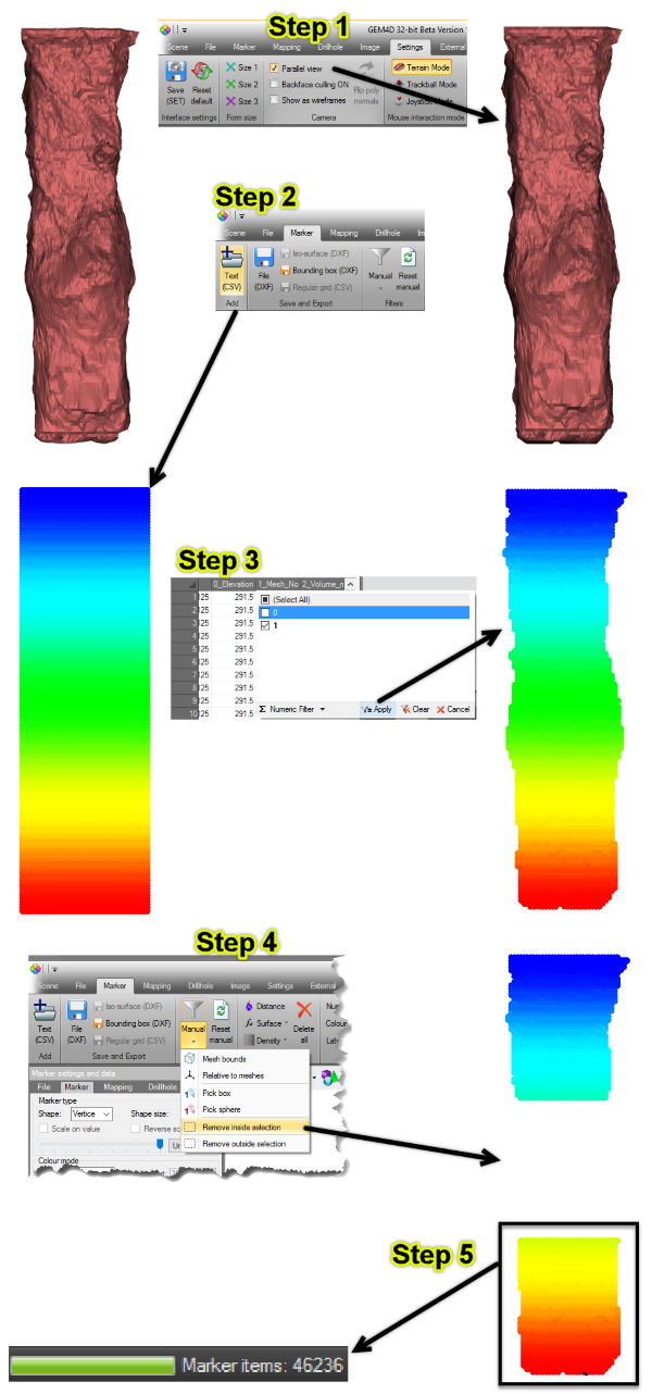
The strength of the block volume model estimation method is that the CSV-points can be loaded as Markers. This allows for the deletion of points, addition of points, filtering of points in a selected area etc. As the volume is just the number of points multiplied by the volume of each point, volumes can be customized to a specific requirement, sub-volumes can be calculated etc. Below find the process broken into 5 steps after the mesh of interest was loaded.
Step 1: Convert to parallel view, as that allows for pixel perfect selection during filtering. In "Parallel view" mode, objects do not get smaller further away from the camera.
Step 2: Load the CSV-file created by "Volume from a single closed mesh". All the points that were evaluated are displayed.
Step 3: Filter out the points outside the mesh, marked as "0" in column "1_Mesh_No". this grid filtering works similar to Excel.
Step 4: Filter the points of interest in the scene by mouse picking two points, in the example the points of the second lift of the stope was removed. In the same way, the points from a single stope can be filtered and the volume calculated, using a single triple-lift CMS.
Step 5: The number of remaining points after filtering are displayed in the Status bar at the bottom of the form. As the volume of every point is known, the volume is the number of points multiplied by the volume that each point represents.


Comments